Semiconductor Optical Amplifiers (SOAs)
Similar to regular lasers, but with an optical signal being amplified by stimulating light emission
August 1, 2001

Before reading this you may find the following tutorials useful:
Laser Basics, Raman Amplification, Optical Fiber, Distributed Feedback (DFB) Lasers
You are driving along the road, regularly checking your rear-view mirror to see what is going on behind you. Your car has this mirror and you are making good use of it, just as a laser makes good use of the mirrors on its ends. Out of nowhere, a car pulls out in front of you, almost sending you piling into the back of it. You slam your brakes on just in time to prevent an accident. The driver who pulled out obviously did not use a rear-view mirror, or maybe it was obscured by some extremely fashionable fuzzy dice. This car was like a semiconductor optical amplifier.
A semiconductor optical amplifier works in a similar way to a basic laser. The structure is much the same, with two specially designed slabs of semiconductor material on top of each other, with another material in between them forming the “active layer.” An electrical current is set running through the device in order to excite electrons, which can then fall back to the non-excited ground state and give out photons (“particles” of light).
But there are two key differences. In a standard laser we want very reflective ends to keep light bouncing back and forth within the cavity. So the laser car has a rear-view mirror. With a semiconductor amplifier we need to get the optical signals straight into the cavity and then straight back out again, so we want to avoid light reflecting back into the cavity. This means that we do not want mirrors on the ends, and a semiconductor optical amplifier car has fuzzy dice obscuring the rear-view mirror. Also, in lasers we only want to get light out at one specific wavelength, and we design the device to make this possible (especially in Distributed Feedback —DFB — lasers). In a semiconductor amplifier we want to amplify light at as many wavelengths as possible. This is because we will have an incoming optical network signal that may have many different wavelengths that all need to be amplified at the same time.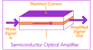 The excited electrons in the semiconductor are now stimulated by incoming light from optical signals to move down to their ground states. The photon given out by an electron losing energy from its excited state exactly matches the photon that caused the emission in the first place. Therefore, there are now two photons representing one particular section of a signal where previously there was only one — hence, the signal has been amplified. These two photons can now cause more stimulated emission as they travel down the device, until they all exit together as a successfully amplified signal.
Semiconductor amplifiers do not currently give as much amplification as erbium doped-fiber amplifiers (EDFAs) can at the common 1550-nanometer region of wavelengths. However, they can be designed to amplify around the 1300nm transmission window, which may see them used in networks that use such wavelengths. In fact, as the demand for more wavelengths grows, systems may use both the 1300nm and 1550nm regions and semiconductor amplifiers may have an important role to play in such systems.
Key Points
Similar to lasers, but with non-reflecting ends and broad wavelength emission
Incoming optical signal stimulates emission of light at its own wavelength
Process continues through cavity to amplify signal
Can be designed for amplification around 1300nm or 1550nm
Further Reading
Erbium Doped-Fiber Amplifiers (EDFAs), Raman Amplification
You May Also Like
