WiMax goes mobile – with QOS * Does it challenge 3G QOS? * How does it work? * Vendor differentiation
September 10, 2006

WiMax – a.k.a. the Institute of Electrical and Electronics Engineers Inc. (IEEE) 802.16 Wireless MAN technology – took a big step forward in February 2006 with the publication of the 802.16e amendment, Physical and Medium Access Control Layers for Combined Fixed and Mobile Operation in Licensed Bands. This mouthful may well announce the imminent arrival of Ethernet’s tanks on the front lawns of the 3G operators, as it extends the industry’s best-bet heavyweight metro broadband fixed-wireless access standard to nomadic and fully mobile terminals. And it does it with an extensive range of quality of service (QOS) capabilities.
These QOS capabilities matter enormously. Without sophisticated QOS, many wireless services – from legacy data services to complex interactive IMS-based services – don’t work as well as they could.
But QOS in broadband wireless access is a difficult and complicated business, as it adds an unpredictable radio link and potentially heavy user contention to the usual non-deterministic behavior of IP packet networks. Carriers therefore need to be aware of how QOS works – and what it can do – in the different flavors of 802.16, and how it relates to the more familiar 3G technologies.
And it’s crucial to understand the extent to which 802.16 allows vendors wide scope for innovation in implementing improved algorithms for better QOS.
This report aims to highlight the importance of over-the-air QOS in the WiMax operator business case, and to look at the options for implementing QOS capabilities in WiMax base-station equipment. Here’s a hyperlinked contents list:
Page 2: WiMax Standardization
Page 3: QOS in Wireless Systems
Page 4: The Wireless MAC Layer
Page 5: 802.16 Physical Layer
Page 6: WiMax QOS Architecture
Webinar
This report is based on a Webinar, WiMax & Quality of Service, moderated by Gabriel Brown, Chief Analyst, Unstrung Insider, and sponsored by Freescale Semiconductor Inc. . An archive of the Webinar may be viewed free of charge by clicking here.Related Webinar archives:— Gabriel Brown, Chief Analyst, Unstrung Insider
Next Page: WiMax Standardization
WiMax is based on the 802.16d (or more formally 802.16-2004 or European Telecommunications Standards Institute (ETSI) HiperMAN) and 802.16e standards published in 2004 and 2006, respectively. The scope of these standards is fairly broad, but it is important to remember that they address only Layers 1 and 2 of the network. Higher-layer network architectures and interfaces are not defined by these standards, unlike the situation in the 3GPP and 3GPP2 specifications for 3G mobile networks, for example.
To address this gap, the WiMAX Forum is developing a core-network architecture as well as specifications for functions such as Radio Resource Management. This is in addition to the well known work in developing interoperability and conformance test profiles, and the associated WiMax equipment certification program. So WiMax is being subject to an essentially full system-level standardization effort, especially in relation to mobility and some of the more advanced applications that WiMax is likely to support in the future.
But WiMax quality of service (QOS) depends crucially on the 802.16 Layers 1 and 2, as these govern the all-important base-station/user-terminal radio access – an inherently difficult environment compared to, say, a wireline broadband network. Because the d/e forms of 802.16 are aimed at different applications – fixed terminals only and mobile terminals, respectively – there are significant differences in technology between them. In particular, 802.16d used Orthogonal Frequency Division Multiplexing (OFDM or ODM for those in a hurry) and 802.16e uses Orthogonal Frequency Division Multiple Access (OFDMA or ODMA). The capabilities of these technologies have a direct impact on end-user services and QOS.
802.16 Key Features
Table 1 summarizes some of the key technical features of the fixed and mobile forms of 802.16. Two basic characteristics are a radio interface that uses adaptive modulation to adapt performance to the prevailing channel conditions of the user, and OFDM techniques to reduce the impact of multipath interference. This make WiMax suitable for near- and non-line-of-sight environments, such as urban areas.
Table 1: Some Features of Fixed & Mobile WiMaxWiMax Fixed (IEEE 802.16-2004/ETSI HiperMAN)
WiMax Mobile (802.16e)
Frequencies specified as sub-11GHz
Frequencies specified as sub-6GHz
Scaleable channel widths specified (1.75MHz to 20MHz)
Scaleable OFDMA 128, 512, 1024, 2048 (not 256)
256-carrier OFDM
Subchannelization
FDD and TDD multiplexing
Questions over backward compatibility (256-carrier OFDMA not specified)
Deterministic QOS
Adaptive modulation (BPSK/QPSK/16QAM/64QAM)
Uplink subchannelization
Source: Light Reading, 2006
Another important feature is the 802.16 media access control (MAC), which, if required, can offer deterministic QOS. This is crucial, because it makes it practical to offer services such as voice and T1/E1-type services. The 802.16e revision was important primarily because it introduced the new physical layer based on OFDMA, but with variable subcarrier permutations from 128 carriers to 2048 carriers. This is sometimes called scaleable OFDMA (SOFDMA), since the number of subcarriers would typically scale with the channel bandwidth. Bandwidth scaleability is one of the most important advantages of OFDMA.
As the WiMAX Forum observes:
The fundamental premise of the IEEE 802.16 MAC architecture is QoS. It defines Service Flows which can map to DiffServ code points or MPLS flow labels that enable end-to-end IP-based QoS. Additionally, subchannelization and MAP-based signaling schemes provide a flexible mechanism for optimal scheduling of space, frequency, and time resources over the air interface on a frame-by-frame basis. With high data rate and flexible scheduling, the QoS can be better enforced. As opposed to priority-based QoS schemes, this approach enables support for guaranteed service levels including committed and peak information rates, latency, and jitter for varied types of traffic on a customer-by-customer basis.[WiMAX Forum, May 2006, Mobile WiMAX – Part II: A Comparative Analysis]
WiMax and Mobile Evolution
In some ways, WiMax can be considered as an early version of the next generation of mobile (or at least nomadic, with no cell handoff) wireless systems. Figure 1 shows an evolution of several different mobile systems all converging on an air interface based on OFDM and on an all-packet-switched core network.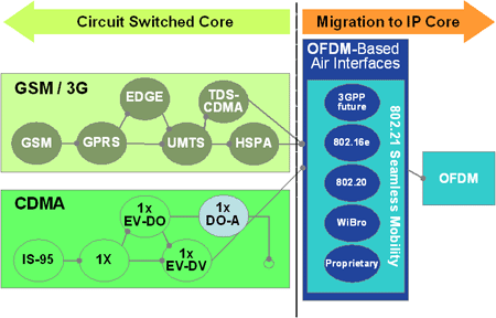 On the radio side there is widespread support for adopting OFDM in the long-term evolution of 3G, for example, and at a high level there are similarities between WiMax and proposals for 3G long-term evolution. However, it is necessary to be careful about grouping all wide-area OFDM technologies together, for there are likely to be substantial differences in detail between the 802.16 of today and the 3G of tomorrow.
On the network side there is also an industry-wide appetite for simplifying mobile networks towards flatter, all-IP architectures, which would reduce costs, increase efficiency, and enhance the scaleability of the mobile core network. To some extent, WiMax moves closer to this goal – it was designed, for example, with IP from the base station from day one, in contrast to the TDM circuit-switched approach used in current cellular systems.
Next Page: QOS in Wireless Systems
QOS means different things to different end users, as much depends on the application and the use to which the end user is putting it. It’s therefore usual to employ a range of measurable performance parameters from which those appropriate to the particular end user can be selected. These parameters are most commonly:Bandwidth
Latency
Jitter
Reliability
An obvious question for WiMax is where the technology fits in with other wireless access technologies (such as 3G and WiFi), but also with fixed-line technologies (such as DSL or fiber), since WiMax has fixed-access applications.
Bandwidth – the unit-time packet throughput – is probably the most basic QOS parameter for many end users, and is obviously limited by the physical-layer pipe between the base station and the client terminal in WiMax (and other wireless technologies), and also by the number of clients that are active in parallel, since the overall system bandwidth is shared. Generally, if the overall bandwidth of a given system is big enough, some of the other QOS parameters will be less of an issue. For example, with enough bandwidth, access contention among different users is eliminated, which simplifies protocols and reduces latency.
“Other parameters, such as latency and jitter, only come in once you are servicing multiple users in parallel and groups of subscribers to the system,” says Wim Rouwet, Applications Engineer, Network and Computing Systems Group, Freescale Semiconductor Inc. .
He points out that latency – the end-to-end packet transmission time – is caused by the granularity of the physical-layer chain, and is typically almost 5ms in 802.16 systems. Latency is also affected by how packet queuing, various QOS protocols, and user characterizations are implemented.
Jitter – the variation of latency over different packets – has to be limited by packet buffering. Since the buffer on the mobile terminal is likely to be small, jitter control in wireless networks tends to fall onto the base station, which has to ensure that different packets receive different prioritization if necessary.
Reliability – the proportion of successfully delivered packets – leads to more complications in wireless networks than in fixed-line ones, and the problems are specifically acute in mobile networks. The issue is that wireless networks have an inherent unreliability because of the vicissitudes of radiowave propagation – especially to mobile terminals with small antennas and low powers in cluttered environments such as urban areas. So packet loss (and numbers of errored packets) will be higher than for fixed-line networks.
This produces a particular problem for wireless IP networks. In a wired IP environment, the physical connection between two stations is more or less errorfree. If there is a packet loss end-to-end, it’s then a pretty safe bet that the loss was deliberate – caused, for example, by a midpoint router dropping a certain packet because of congestion within the network. Such midway deliberate dropping of packets is used in turn by end-to-end protocols, such as Transmission Control Protocol (TCP), as a signal to adapt end-user packet traffic to the available network bandwidth.
TCP has two main tasks:Provide reliability by controlling end-to-end retransmission of errored or lost packets
Provide throttle control by limiting connection speed to maximum speed of transport medium.
So, if TCP detects a packet loss, it assumes that a router in the middle of the network dropped that packet on purpose. At that point, TCP will assume that the network was congested, it will lower the end-user transmission speed, and it will also retransmit that packet. By lowering the transmission speed, TCP thus tries to even out the bandwidth given to the end user.
“The problem with TCP is that, as soon as that packet drop occurs in a wireless system, you cannot be sure that it was deliberate. Even worse, there is a very high probability that it wasn’t deliberate, because a wireless environment is not as secure as a wired environment. So, in such a case, the TCP protocol, by lowering the transmission speed, actually does the opposite of what it should do,” says Freescale's Rouwet. “One of the many jobs that the wireless MAC layer has is to overcome this problem.”
Figure 2 shows the unfortunate effect (known as the TCP packet-loss problem) that results. The window size is the size of the buffer on the receiving device; TCP sends this figure to the transmitting device, which in turn will send only enough bytes to fill the window before pausing and waiting for an acknowledgement of successful reception to resume transmission. TCP throttles back the transmission rate under the assumed congestion by reducing the window size, and this causes the radio link to be underutilized.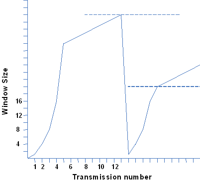 Fortunately, there are ways round this problem – one being to enhance the wireless MAC layer.
Next Page: The Wireless MAC Layer
In a wireless network, the MAC layer has the following main tasks:Adaptation of higher-layer packet size to physical-layer packet size
Addition of security through encryption
Packet-header compression for higher physical-layer efficiency
Reliability through providing retransmission of lost/errored packets
QOS through scheduling protocols for packet prioritization to guarantee latency and jitter limits under congestion
“If the MAC layer can provide reliability, the base-station side does the packet retransmission when needed, so you can circumvent the problem of TCP having to do suicide algorithms to lower its transmission speed,” says Freescale’s Rouwet. “Also, we all learned a lesson in 802.11 [WiFi], and it is a very key area to make sure that there is secure data transport between the base station and the client.”
Not surprisingly, the different wireless technologies – WiMax, 3G, and WiFi, for example – have different MACs, capable of supporting different tasks. Table 2 summarizes some of the MAC/silicon characteristics of these technologies.
Table 2: Key Wireless Technologies & Their MAC Characteristics3G HSPDA
3G EV-DO
WiMax 802.16.2004
WiMax 802.16e
WiFi
Bandwidth, MHz
5
1.25
<20
<20
20
Data rates, Mbit/s
14.4
2.4
75
75
11, 54
bit/Hz
2.9
1.92
3.75
3.75
2.7
Multiple access
TDMA, CDMA
CDMA
OFDMA
OFDMA
CSMA/CA
Duplexing
FDD
FDD
TDD/FDD/HD-FDD
TDD
Mobility
Full
Full
Portable
Nomadic/Full
Portable
Coverage
Large
Large
Mid
Mid
Small
Source: Freescale Semiconductor, 2006
It’s fairly clear from this perspective that the two 3G technologies and WiFi are very different and occupy opposite poles as far as mobility and (current geographical) coverage are concerned. WiMax is more in the middle. However, because of the efficiency of its air interface, and also because of the channel sizes used, 802.16 supports higher data rates than both 3G and WiFi. Also, says Rouwet, 802.16 has been very well designed as an IP-based network, which allows a very high level of QOS.
Because of the basic nature of the wireless MAC-layer main tasks, it’s not surprising that there is a lot of functional commonality among different access protocols such as 3G UMTS Release 4/5 and 802.16. For example:Automatic Repeat-reQuest (ARQ) – Handled by RLC layer in UMTS, and by MAC-CPS in 802.16
Ciphering – Handled by RLC or MAC layer in UMTS, and by MAC-CPS privacy sublayer in 802.16
QOS – Handled by proprietary scheduling algorithms
Fragmentation and/or packing – Handled by RLC layer in UMTS, and by MAC-CPS in 802.16
Also, some physical-layer functionality is supported in optional implementations or new revisions of 3G UMTS Release 5 and 802.16:
Hybrid ARQ (H-ARQ) – Used in UMTS Release 5, but is optional in 802.16e. There are various forms of H-ARQ (usually involving some form of automatic error correction), which give better performance than basic ARQ, although at the cost of greater complexity.
Adaptive Modulation and Coding (AMC) – Used in both UMTS Release 5 and 802.16 to vary the transmission mode and coding to match changes in the radio channel conditions.
Figures 3 and 4 show both the UMTS protocol architecture and a comparison with that of 802.16. They make it easy to see that essentially similar things are going on in each architecture, although the ranges of some of the protocols are different.
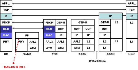
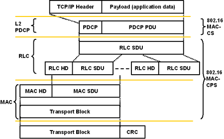 Thus, for example, the 802.16 MAC-CPS parallels to the MAC and RLC (Radio Link Control) in UMTS, whereas the 802.16 MAC-CS parallels to the L2 PDCP (Packet Data Convergence Protocol, which handles IP header compression and decompression, and sequence numbering among other tasks) in UMTS.
MAC-Layer Challenges
In UMTS, the Radio Network Controller (RNC) essentially takes care of the whole MAC-layer protocol. However, locating the MAC layer in the RNC has a big downside – namely the delay between the RNC and user terminal, which typically can be up to 100ms. Such high levels of delay would prevent H-ARQ, AMC, and fast scheduling from working, so UMTS Release 5 has to get around this by effectively splitting the MAC-layer implementation between the RNC and the Node B, where:RLC remains in RNC – handling fragmentation, packing, ciphering, scheduling, and ARQ
MAC-D remains in RNC – mapping logical channel to appropriate transport format
MAC-HS goes to Node-B – handling H-ARQ support, fast scheduling, and AMC control
802.16 takes a different approach, and implements the complete MAC layer in the 802.16 equivalent to the UMTS Node B. So there is no longer an RNC entity, only the MAC-CS and the MAC-CPS.
“By doing that, the overall MAC layer end-to-end becomes a little less complex, because you don’t have a system with two different boxes that have to talk to each other,” says Rouwet. “On the other hand, you do include more and more complexity of the MAC-layer functions that have to be done at the base station, and that adds complexity to the system.”
Another potential negative could be that, in UMTS, the RNC provides an ideal platform for handling handovers between base stations, because it forms a central point of control. In 802.16 that central point is absent, so handoff complexity could become an issue.
Next Page: 802.16 Physical Layer
To understand the workings of the 802.16 MAC layer, it’s necessary to have a basic understanding of what is going on in the 802.16 physical layer (PHY). Figure 5 shows the processing steps of the OFDMA PHY used by 802.16.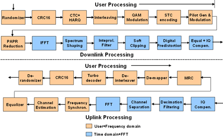 In the downlink process, packets arriving from the MAC layer are subject in sequence to randomization, forward error correction, and coding (such as CTC, a convolutional line coding). Then follows interleaving and modulation, and eventually a key block of any of the processing – the Inverse Fast Fourier Transform (IFFT), which moves the signal from the frequency domain to the time domain. After that, follows time-domain processing (the blue blocks in Figure 5, such as spectral shaping). Finally, there is a link into the IF and RF interfaces.
The uplink process is essentially the opposite – so a Fast Fourier Transform (FFT) moves the signal from the time domain to the frequency domain, and so on.
Figure 6 shows how the OFDM PHY layer maps into a logical structure that represents the frame. On the horizontal axis, every small interval is a single instance of the FFT. On the vertical axis are all the subcarriers. These are not logical subchannels, so it isn’t necessary to calculate the 256 additional carriers.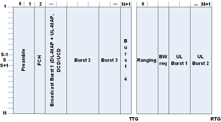 Multiple instances of the FFT can be put together and concatenated into what the MAC perceives as a burst, and bursts are scheduled for use by users – burst 2 can go to user 1, burst 3 to user 2, and so on. Burst 1 is the broadcast burst (received by all user stations), which contains a downlink and uplink MAP (Media Access Protocol) messages, which are essentially a table of contents for the remaining part of the frame. Each frame starts with a preamble which allows the client stations to synchronize with the base station.
In the example frame shown, the left-hand side is the downlink and the right-hand side is the uplink. The essential point to notice is that the bursts form a sequence of vertical strips across the whole frame, giving a quasi-1-dimensional structure. This follows from all the subcarriers for an FFT instance being allocated to the same burst (and hence user), and from bursts being concatenated from contiguous FFT instances.
Things get a little more complex for the OFDMA frame structure, shown in Figure 7. Here, different subcarriers can be allocated to different bursts (users), and the same FFT instance can be allocated to different bursts (users). The result is to imbricate the bursts into a much more obviously 2-dimensional structure, somewhat reminiscent of the classic Tetris computer game.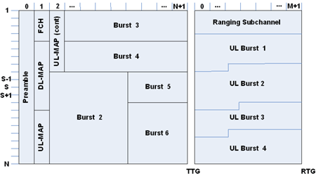 Next Page: WiMax QOS Architecture
The WiMAX Forum Applications Working Group (AWG) has determined five initial application classes, listed in Figure 8. Initial WiMax Forum Certified systems are capable of supporting these five classes simultaneously.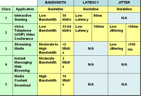 One metric missing from Figure 8 is mobility, specifically the handover between sectors and cells. This is likely to be added in the forthcoming wave of mobile WiMax profiles due to start later in 2006. As luck would have it, the application classes map to the five QOS classes specified in the 802.16 standards, as shown in Table 3.
Table 3: 802.16 QOS ClassesClass
Description
Minimun rate
Maximum rate
Latency
Jitter
Priority
Unsolicited Grant Service
VOIP, E1; fixed-size packets on periodic basis
x
x
x
Real-Time Polling Service
Streaming audio/video
x
x
x
x
Enhanced Real-Time Polling Service
VOIP with activity detection
x
x
x
x
x
Non-Real-Time Polling Service
FTP
x
x
x
Best-Effort
Data transfer, Web browsing, etc.
x
x
x = QOS specified. Source: Light Reading, 2006
A quick rundown of the classes is:Unsolicited Grant Service (UGS) is used for real-time services like T1 and E1 lines, and for VOIP services with fixed packet sizes.
Real Time and Variable Rate is used for real-time services such as streaming video. This offers a variable bit rate, but with a guaranteed minimum rate and guaranteed delay. Another example where this could be used is in enterprise access services. It’s quite popular for fixed wireless operators (or WISPs) to guarantee E1/T1-type data rates with wireline-equivalent SLAs, but to allow customers to burst higher if and when there is extra capacity on the network. This is quite a successful strategy for wireless operators competing against incumbent wireline providers.
Enhanced Real-Time Variable Rate is specified in 802.16e, and will be used for VOIP services with variable packet sizes as opposed to fixed packet sizes – typically, where silence suppression is used. This will include applications such as Skype – and partly explains why 802.16e equipment isn’t perhaps as good at supporting VOIP without vendor-specific tweaks to the standard MAC – which obviously some of them do.
Non-Real-Time Variable Rate is for services where a guaranteed bit rate is required, but guaranteed delay isn’t. This might be used for file transfer, for example.
Best-Effort is the old standby for email and browsing and so forth, and is largely what people have on a DSL line at home today.
Scheduling Algorithm
The really big question is – how do you map radio resources to a user’s service classes? This is the task of the scheduling algorithm, which is likely to be a key area of differentiation among base-station equipment vendors. To a degree, this is seen in the 3G HSPDA systems being rolled out currently – the performance of the scheduler is a potential differentiator among equipment providers in what is otherwise a quite standardized environment, as it helps operators use spectrum more efficiently and deliver better services.
In simplistic terms, for, say, downlink operation, packets arrive from the network at the base station, and are placed in downlink user traffic queues. The scheduler decides which user traffic to map into a frame from the queues, and the appropriate burst is generated, together with the appropriate MAP information element. Users are scheduled according to their service classes (UGS, rtPS, ertPS, nrtPS, and BE). MAPs contain information on transmission to/from all users for each frame, including modulation and coding type, and size and position of allocation.
Scheduling in this way on a frame-by-frame basis gives a lot of flexibility, but it does create issues, particularly in the frame allocation overhead needed (shown in red in Figure 9 for OFDMA).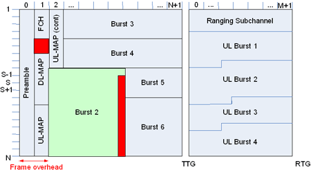 “You can schedule a single user using either a single slot or the complete frame, depending on your scheduler choice,” says Freescale’s Rouwet. “The problem from that is that, by not fixing anything beforehand, you have to build a fairly extensive table of contents by the download MAP to show where a user should look in the frame to listen to the data being transmitted by the base station... The problem is that the downlink MAP has to be listened to by every user, which means that it has to be in a quite robust modulation and encoding type. And, in a VOIP system, where you have a lot of users, the MAP actually gets quite big.”
A further issue is the amount of padding bytes needed to ensure that each burst forms a rectangle that can be packed correctly into an OFDMA frame. Ideally, to maximize transmission efficiency, the number of padding bytes should be zero, but this may not be possible, and will depend on the number of users, their QOS and the applications they are running – and, of course, on the decisions the scheduler is taking. So WiMax operators may face tradeoffs between transmission efficiency and service offerings, depending on the scenarios they plan to support.
OFDM and OFDMA Compared for QOS
Generally speaking, OFDM allows a simple, relatively straightforward scheduler design, giving good performance for larger packet sizes, as the overhead/padding problem isn’t so important. This makes it suitable for the needs of certain data services, such as legacy TDM. However, a larger packet size increases the latency of the connection, which can be an issue.
OFDMA, on the other hand, gives a smaller granularity of bandwidth grants than OFDM, so there is less overhead wasted for small packet sizes. Similarly, the smaller granularity of MAPs means that less overhead is wasted in MAP allocation. Also, OFDMA has the potential for using AMC in "fixed" environments with known channel responses – it can, for example, pre-allocate specific subchannels that have a known good performance over the physical layer to a certain user.
However, this use of AMC has the drawback that, by reserving certain subchannels for one user, it reduces the pool of subchannels available to other users, and therefore limits the scheduler’s flexibility and dynamic range.
You May Also Like


