The first independent test of the Cisco CRS-1 * Tbit/s of bandwidth * Millions of routes * Tens of millions of flows
November 30, 2004

$500 million. Four years of R&D. 500 people.
If it took all of this for Cisco Systems Inc. (Nasdaq: CSCO) to build its CRS-1 router, what in tarnation would it take for us to test it?
Roughly speaking, this was the question that occupied the staff of European Advanced Networking Test Center AG (EANTC) when we first received the commission from Light Reading, earlier this year, to test Cisco’s (and the world’s) first ever 40-gig-capable core router.
And it turns out that our trepidations were nothing if not well founded. Testing IP traffic at 40 gigabits per second is not a straightforward task, to put it mildly. One contributor to the project described it as �“trying to measure lightning bolts. In mid-air” – which we think is as good a way as any to characterize the sheer speed and power of the equipment under evaluation. Consider:
Developing the test methodology alone took over two months.
Testing partner Agilent Technologies Inc. (NYSE: A) dedicated five person-months worth of engineering in their labs in Australia and Canada to create individual test procedures matching the test plan requirements.
The test itself took place during a monumental, two-week, 140-hour session, involving a total of 11 engineers.
More than 50 Agilent OC-192 (10 Gbit/s) plus two extremely rare OC-768 (40 Gbit/s) test ports were lined up for the test. (Securing the latter was a feat in itself, since Agilent is the only analyzer vendor manufacturing them today, and fewer than ten of these modules exist worldwide.)
The raw EANTC test documentation consisted of Excel sheets totaling more than 700,000 lines.
In the end, all of the effort (and angst) that went into this independent verification of Cisco’s brand new CRS-1 core router was well worth it. This test represents several industry firsts: the first test of 40-Gbit/s Sonet/SDH interfaces; the first to achieve more than 1.2-Tbit/s emulated Internet packet throughput; and the first to publish independent test results of the Cisco CRS-1 at all.
So how did Cisco’s router fare? The Reader's Digest version is this: The CRS-1 performed extraordinarily well, demonstrating that it can scale to meet the requirements of service providers far into the future. It scaled to terabits-per-second of bandwidth, millions of routes, and tens of millions of IPv4 and IPv6 flows. Software upgrades interrupted the traffic for only nanoseconds – even on a fully loaded, live chassis. Its high-availability features are simply superb. And we even confirmed that its throughput capabilities scale to multi-chassis configurations.
In the opinion of EANTC, the CRS-1 proved itself to be the next milestone in router performance and scaleability.
But why test 40-gig at all?
While the IT industry may not be growing as rapidly as it once was, the Internet still is. Many large service providers have been delaying investments in new core network infrastructure in the past years – but now that much of the equipment installed during the Internet boom has been written off, and as capacity requirements continue to ramp, they have little choice but to think about deploying the next generation of backbone routers.
This is generating a demand for new monster boxes – ones that reach new levels of forwarding speed and interfaces. Products that invoke packet-over-Sonet (POS), ultra-broadband, 40-gig hardware potentially offer a solution to service providers’ needs today that is easier to manage and uses fiber infrastructure more efficiently than products that deploy 10-Gbit/s interfaces in clumps. And 40-gig has the added benefit of future-proofing carrier networks for tomorrow. While the addressable market for such technology is small today, the history of growth in telecom networks shows that it will inevitably grow in size and importance over time.
Cisco’s solution for this market, the CRS-1, employs parallel packet processing technology implemented in part within highly specialized application-specific integrated circuits (ASICs). It claims the result is an architecture that ensures non-blocking, parallel, high-availability packet processing in each card and throughout the fabric. (See Cisco’s CRS-1 chassis description for details.)
We were eager to verify Cisco's claims.
It should be mentioned that Light Reading’s original goal in undertaking this test was not to test the CRS-1 in particular, but rather to test all 40-gig-capable routing platforms, from any vendor.
However, an analysis of the available 40-gig products produced a short-list of exactly one: the Cisco CRS-1 Carrier Routing System. (Note: Avici and Juniper, Cisco’s principal competitors, both say they have 40-gig “in the works.”)
Similarly, working out which device to use to test the CRS-1 was pretty simple. The number of testers that can analyze 40-gig can also be counted on the fingers of one, well, finger: the N2X multiservice test solution from Agilent.
While identifying which product to test and which tester to use were straightforward tasks, convincing Cisco Systems to allow Light Reading to conduct a completely impartial evaluation of its Crown Jewel was anything but.
This is to be expected. Much is at stake. The CRS-1 is hugely important to Cisco and its customers. Not only is it the first 40-Gbit/s router, it also is the first Cisco router to use a completely new “carrier-class” iteration of Cisco’s IOS router code (code that ultimately will be retrofitted across other Cisco router platforms). And it also holds huge significance as Cisco’s most important attempt to date to convince carriers that it truly understands their needs and can deliver the linchpin supporting advanced telecom networks carrying next-generation voice, video, and data service traffic.
Protracted United Nations-like negotiations were undertaken over a period of several months between Cisco and Light Reading. In the great tradition of American arbitration, voices were raised, feelings were hurt, but an agreement was finally struck based on some agreed-upon ground rules, the most important of which were:
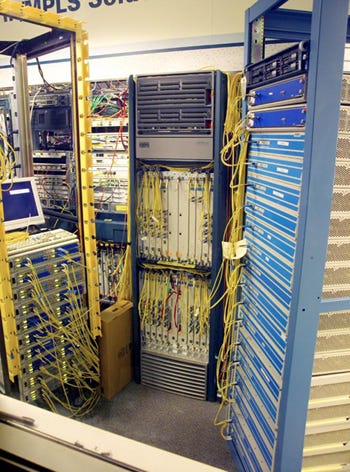
It was agreed that the test would take place at Cisco’s facility in San Jose, Calif., rather than EANTC’s location in Berlin (a point we ceded for the logical reason that the CRS-1 requires a big rig and a small army of technicians to move it from place to place).
As with all Light Reading tests, Cisco would not contribute to the funding of the test project, at all, in order to ensure its independence.
Prior to publication, Cisco would be allowed to review the raw test data and to point up any anomalies, but it would not be permitted to read EANTC’s analysis of its product’s performance, and it would have no “right of veto” over the publication of any results.
Most importantly of all, all parties agreed that the methodology for the test would undergo peer review by a group of leading service providers, ensuring that both the tests and the results they produce are realistic and reflective of both real-world network conditions and carrier requirements.
The complete test methodology can be downloaded here; and the service providers' feedback can be viewed here. The end result is a methodology that is not tailored or customized around the Cisco CRS-1 in particular, but can be run with any equipment matching the basic physical layer requirements.
Based on the service providers' feedback, we identified eight key areas to test that focus on both current and future service provider requirements for IP core backbones:
IPv4 (the current Internet protocol) forwarding performance, emulating 15 million users with realistic traffic patterns;
Mixed IPv4 and IPv6 (new Internet protocol) forwarding performance, verifying the router’s preparedness for the transition to the next-generation Internet protocol;
The impact on forwarding speed when adding security services like access control lists, logging of unauthorized traffic streams, and quality-of-service classification;
Routing update performance when connected to other backbone routers via eBGP (exterior border gateway protocol), exchanging more than 1.5 million unique routes;
Scaleability for multicast applications like TV broadcasting and enterprise point-to-multipoint applications; loading the router with a massive 70 percent to 30 percent multicast/unicast packet mix in 300 multicast groups;
Evaluation of the class-of-service implementation, again servicing millions of emulated users;
The reality of high availability (hitless) software and hardware exchange claims – a must for a core router today;
Finally, a Multiprotocol Label Switching (MPLS) tunnel scalability test to evaluate the capability of the system to work as a Label Switch Router inside an MPLS core network.
Of course, there were plenty of other aspects of the Cisco CRS-1 that would have been nice to test, but were not practical to undertake. In particular, testing a network of multiple Cisco CRS-1s, rather than a single unit, would have provided valuable insights into its performance in real-world conditions. But the resources needed to do this – in terms of available CSR-1s, test equipment, and time and money – made this impossible. As already noted, testing a single CRS-1 pushed limits as it was.
So how did the Cisco CRS-1 perform in all these tests? Frankly, we were amazed by its speed, scaleability, flexibility, and the all-around robustness of the system. Based on our results, the CRS-1 is truly a 100 percent carrier-grade router.
Key findings include:
Wire-speed IPv4 forwarding performance with 15 million emulated users (flows) on both OC-192 and OC-768 interfaces, with a total of 929 million packets per second (640 Gbit/s) in a single chassis configuration and 1.838 billion packets per second (1.28 Tbit/s) in a multi-chassis configuration (see Test Case 1)
Wire-speed forwarding performance with mixed 85 percent IPv4 and 15 percent IPv6 traffic (see Test Case 2)
Forwarding performance unaffected by adding 5,000 access lists per port, access list logging, and QOS classification (see Test Case 3)
Only 18 seconds to reconverge after rerouting 500,000 routes to different ports, out of a total of 1.5 million IPv4 and IPv6 routes (see Test Case 4)
Zero-loss multicast forwarding performance at 400-Gbit/s total multicast throughput (see Test Case 5)
Premium-class (strict priority) and weighted fair queuing up to the specification in a wire-speed COS test, both with fixed bandwidths and with traffic bursts (see Test Case 6)
Only 120 nanoseconds service interrupt during a software package upgrade; hitless hardware exchange for all but fabric card exchanges; 0.19 seconds recovery time after a fatal error of one of the eight back-plane fabrics (see Test Case 7)
Wire-speed forwarding over 87,000 MPLS tunnels in total (1,500 per port); including correct traffic engineering for explicit forwarding (EF) and best-effort differentiated services (see Test Case 8)
So did the CRS-1 perform flawlessly? Not quite. An instance of IPv6 packet loss during testing needed to be corrected via a micro-code fix, but from a technical point of view this is a real pick. Also, in terms of form factor, we believe the CRS-1 chassis is impractically large for use at installations where only one or two linecards are required. Industry scuttlebutt has it that Cisco is working on a half-size version of the product that will nix this issue.
This test is significant for a number of technology “firsts,” but it represents another type of “first” also: It’s the first time that Cisco has allowed Light Reading to test one of its products since a – ahem – rather controversial router test undertaken by the publication back in 2001. We believe the results of this test confirm the wisdom of this bold move on Cisco’s part. We also hope that its decision encourages other router vendors to step up to the plate for Light Reading’s 2005 program of tests, which will be announced in January.
The following pages describe the tests, and the results for each, in more detail.
Next Page: Test Setup
— Carsten Rossenhövel is Managing Director of the European Advanced Networking Test Center AG (EANTC), an independent test lab in Berlin, Germany. EANTC offers vendor-neutral network test facilities for manufacturers, service providers, and enterprises. In this role, Carsten is responsible for the design of test methods and applications. He heads EANTC's manufacturer testing and certification group.
The Cisco CRS-1 was tested in the following configuration:
A total of 56 packet-over-Sonet OC-192 (10 Gbit/s) interfaces and two packet-over-Sonet OC-768 (40 Gbit/s) interfaces were used for the test. On the Cisco router, each module has four OC-192 ports or one OC-768 port.
Only true Sonet OC-768 – a.k.a. SDH STM-256 – interface modules were allowed to participate in this test. 4x OC-192 WDM ports are not considered true OC-768 interfaces.
The CRS-1 chassis and the OC-192 and OC-768 interface modules all used Cisco IOS-XR software version 2.0.2. IOS-XR is a completely renewed variant of the IOS operating system. For more details about IOS-XR see the Hardware & Software Availability Test.
Cisco had to choose one single software release for all tests. During the test session, software was not exchanged (except for the software upgrade test and the multi-chassis tests, and a patch required for Test Case 2). Only production releases were allowed. At the beginning of the test, EANTC downloaded the software from Cisco’s public Website.
A cluster of Agilent N2X systems (former RouterTester, software release 6.3) with 40 OC-192 interfaces was used for the test, as well as a second cluster of Agilent RouterTester systems (software release 5.1.1) with 16 OC-192 interfaces and two OC-768 interfaces. We used different clusters because the Agilent 40-Gig port supports only the old software.
All Cisco configuration changes and all CRS-1 console messages were logged by EANTC automatically, to ensure that the tests were run in a completely reproducible environment.
Each test was carried out with the emulators connected to the same physical ports. Analyzer ports and traffic streams were interleaved in a way that both the CRS-1’s back plane and its modules’ internal processing units were stressed. Cisco stated that there is no performance difference between traffic remaining in one module and traffic traversing the back plane anyway; our tests were set up to verify this.
We used a standard IPv4 and IPv6 address plan for all test cases; each interface had a class A network address space to fit all the routes and flows. Please see the complete Methodology for details.
Next Page: IPv4 IMIX-Based Forwarding
Test Objective
Determine the maximum IPv4 forwarding performance of the system under test under realistic conditions.
Test Setup
For detailed information on the test setup, please see the complete Methodology, page 18.
Verifying the maximum bandwidth is the simplest thing everybody usually starts with. But here, we were faced with the targeted bandwidth and with the number of calculated user flows traversing the router simultaneously. The theoretical maximum bandwidth is 40 Gbit/s (full duplex) per module, 640 Gbit/s per chassis, and 92 Tbit/s in the largest possible CRS-1 multi-chassis configuration. We were able to load one fully populated single-chassis with the Agilent interfaces we had available: 56 x 10-Gig plus 2 x 40-Gig equals 640 Gbit/s. This is probably one of the most massive amounts of IP traffic ever emulated.
To extend the scaleability tests even further, a multi-chassis CRS-1 configuration was constructed using the same interface cards as before, plus an additional 88 OC-192 (10-Gbit/s) and 10 OC-768 (40-Gbit/s) interfaces, which ran a snake test looping emulated traffic multiple times through the chassis. This router installation, filling three racks, included two linecard chassis and a fabric card chassis to interconnect them.
The number of emulated users was our second challenge. Many tests employ only a few huge bandwidth “flows” (end-to-end IP address relationships), each with a huge bandwidth. These are easier to handle for some router architectures because the size of a flow table (if such state is kept) is small, and accessing entries is fast. For a realistic scenario however, we assumed that each user takes only 42-kbit/s bandwidth – some might do more, some less. (See the QOS Test for burst performance.) To fill 640 Gbit/s, 15 million such flows are required. We configured static IP routes to the destination IP networks containing the emulated users. (BGP was used in later test cases.)
This number of flows exceeds today’s requirements by far, and, according to carrier feedback, is a good number.
All load tests used a mix of packet sizes, representing Internet mix traffic (IMIX). This is a deterministic way of simulating real network traffic according to the frame size usage. Some studies indicate that Internet traffic consists of fixed percentages of different frame sizes. IMIX traffic contains a mixture of frame sizes in a ratio to each other that approximates the overall makeup of frame sizes observed in real Internet traffic. Using IMIX traffic allows us to test the SUT under realistic conditions, as compared to single packet sizes tested sequentially.

On packet-over-Sonet links, byte stuffing on the physical layer (HDLC) influences the maximum achievable bandwidth. Because the router will modify the IP header (TTL) and the checksums, it will potentially generate byte stuffing in addition to what it received, leading to a situation where the router needs to send more than what was received.
Results
We ran the test twice, in different hardware configurations. In the single-chassis version, the router reached wire-speed IMIX forwarding with a total of 929 million packets per second, or 640 Gbit/s. We verified that there were no out-of-sequence packets in any flows (which would be harmful to TCP throughput from the end user’s point of view).
In the multi-chassis configuration (for details of the physical setup see test setup page), the system reached the almost unbelievable number of 1,838 million packets per second (yes, that is 1.8 billion pps). The aggregate bandwidth was 1.28 Tbit/s.

Because of the standard packet-over-Sonet byte stuffing (see above), the latency tests were run at 98 percent load. The average of 80 microseconds (µs) for the single-chassis as well as for multi-chassis matches Cisco’s expectations.
The CRS-1 uses a three-stage Benes switch topology that obviously scales very well to many interfaces. The number of three stages remains the same for all chassis sizes. The multi-chassis version requires different types of fabric cards externalizing the second stage, but this is not an architectural difference. As we see, the three stages do not lead to noticeably higher latency than other architectures – 80µs latency is negligible, and a voice-over-IP call would not notice even if there were twenty or more CRS-1s in the connection. The only difference seen between the single-chassis and the multi-chassis solution is the maximum latency, showing differences of +/- 80 µs. Still, the maximum latency is very small.
Next Page: IPv4/IPv6 Mixed Forwarding
Test Objective
Determine the maximum forwarding performance for mixed IPv4 and IPv6 traffic.
Test Setup
For detailed information on the test setup, please see the complete Methodology, page 20.
In 2004, the percentage of IPv6 traffic in the Japanese Internet backbone reached 1 percent of all traffic. A worst-case guess is that IPv6 traffic might reach no more than 15 percent of all Internet traffic until 2010, which is the figure we used in this test. IPv6 is slowly getting rid of its research-network-only image: Carriers now require it for all new backbone equipment.
In our test, the CRS-1 had to prove that it processes IPv6 forwarding purely in hardware, and that the higher overhead to analyze the header does not lead to any performance issues – specifically in a realistic IPv4 and IPv6 environment. We prepared the Agilent emulators as in the first test case; the only difference was to substitute 15 percent of all traffic with IPv6. (The Internet-like mix for IPv6 also used different packet sizes.)
Results
The CRS-1 clearly proved that it processes IPv6 completely in hardware. In our mixed scenario, the single-chassis system mastered a packet rate of 820 million pps at line rate. The packet rate is slightly smaller than in the pure IPv4 scenario because IPv6 packets are longer.
Surprisingly, the system showed 1.83 percent loss in the first test run. Cisco explained that packet flows arriving at the Modular Services Card are processed by a chipset with 188 parallel channels, each of which can deal with one packet at a time. Under normal conditions, this is much more than enough for wire-speed throughput, as we have seen in all the other tests. The forwarding decision for an IPv6 packet takes 20 percent more time than for an IPv4 packet – our latency tests confirmed this value (see below). The scheduler assigning packets to each of the 188 channels has been optimized to perform at wire-speed for most IPv4 and IPv6 combinations. Our 85/15 percent case triggered a corner case by chance.
Cisco optimized the micro-code and installed a patch on the system under test. We reran the test case and verified that the CRS-1 now performed at 100 percent throughput without packet loss. The patch remained installed for all further test cases, to make sure that it didn’t harm the performance in other areas.
Table 1: Mixed IPv4/IPv6 packet rates
Transmit Rate (packet/s total) | Receive Rate (packet/s total) | IPv6 Transmit Rate (packet/s) | IPv6 Receive Rate (packet/s) | Packet Loss per Second | Receive Bandwidth L2 | |
First test run | 819,904,533 | 802,170,750 | 130,840,624 | 115,837,061 | 15,003,563 (1.83 %) | 98.17 % |
Second test run, after micro-code change | 819,927,902 | 819,927,902 | 130,840,608 | 130,840,608 | 0 | 100 % |
The latency tests were run at 98 percent load and showed that the average latency is around 20 percent higher than in a pure IPv4 environment, and the maximum latency in a multi-chassis environment is 25 percent higher than in a single-chassis system. However, it is important to note that all IPv4 and IPv6 packets were forwarded within at most 0.34 milliseconds of time – this was the absolute maximum latency, which is a great result for IPv6.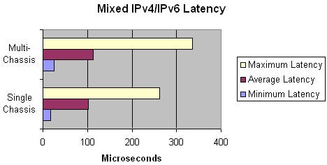
Because of parallel packet processing in the Modular Service Card, we were aware of the theoretical possibility of out-of-sequence packets. EANTC ran a separate test again to verify that all packets within each flow were delivered in the correct sequence. In this test case (and in all of the others, too) Cisco maintained the sequence for each and every flow under any conditions. Also, there were no stray (misrouted) frames or any other unexpected issues. The implementation needs to be credited for the outstandingly precise scheduling in an ultra-high-speed parallel computing environment.
Next Page: IPv4/IPv6 IMIX-Based Forwarding With Security & QOS
Test Objective
Verify that the forwarding performance for mixed IPv4 and IPv6 traffic does not suffer when access control lists, logging, and quality-of-service (QOS) classification lists are configured.
Test Setup
For detailed information on the test setup, please see the complete Methodology, page 22.
Few carriers will run an IP router as a pure packet-forwarding machine. Most need to configure additional packet processing features like differentiated services classification, security (access control filters), and logging of users trying to access unauthorized services (access control list logging). It is a standard requirement for a carrier-class router to perform as well with all these services activated.
Results
We configured a 5,001-entry access control list (ACL) for IPv4, where 5,000 entries were DENY statements and the last entry was a PERMIT-ALL statement. The DENY criteria were chosen as pseudo-random and not sequential, thereby preventing sequential ranges being converted into a single ACL entry. Also, 50 percent of the DENY entries were configured matching the IP addresses of the data streams processed, but not matching the UDP ports of the data traffic. So the router had to process all statements and to look deeply into the packet before it could decide to forward the packet. Furthermore, the ACL was applied as both an ingress and egress filter on each port – requiring that the ACLs were processed twice for each packet.
We configured an identical group of access lists for IPv6.
Next, we configured ACL Logging on the 5,000th ACL entry (both IPv4 and IPv6), requesting the router to log packets matching this entry (to notify the administrator of an attempt to violate the security rules).
Finally, we configured a QOS classification filter with 500 entries for both IPv4 and IPv6 on each interface, emulating a typical edge scenario where traffic coming from customers needs to be assigned to different classes of service.
Now, we set up the IPv4 and IPv6 traffic streams on the analyzer identical to the previous test case, to make results easily comparable. The only difference was that we now sent UDP packets (smallest packet size 48 bytes), forcing the router to inspect the UDP header for access control list processing. The resulting packet rates are a bit lower because the packet sizes had to be increased.
Cisco was sure to reach wire-speed without any degradation compared to the previous results. The result confirms Cisco’s expectations: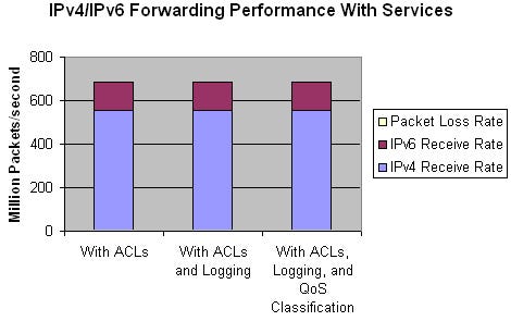
Table 2: Throughput w/ active access control lists, logging & QOS
Tx Rate | Rx Rate | Tx Rate | Rx Rate | Packet Loss per Second | Rx Bandwidth L2 |
684,912,460 | 684,912,460 | 130,839,710 | 130,839,710 | 0 | 100 % |
Here are the results in detail:
The test run with a 5,001 entry ACL for IPv4 and another 5,001 entry ACL for IPv6, where 5,000 entries are DENY and the last entry is a PERMIT-ALL did not show any IPv4/IPv6 packet loss at wire-speed IMIX load.
A second test run confirmed the ACLs are actively protecting the network, when we configured one stream on the analyzer to match one of the ACL entries. Appropriate IPv4 and IPv6 packet drops were encountered across all ports. (The Agilent statistics did not show which of the streams were dropped.)
The CRS-1 forwarded access control logging to a syslog server controlled by EANTC. The logs looked like this:Oct 27 14:33:29.242 : ipv4_acl_mgr[210]: %IPV4_ACL-6-IPACCESSLOGP : access-list IPV4_Test (50400) deny udp 169.0.0.3(0) -> 168.0.0.3(5086), 1 packet
QOS Traffic Classification Lists were active at the same time as the security ACLs. Cisco configured an ingress service policy that utilized a 500-line ACL. A “show policy-map interfaxe…” command was issued to verify that DiffServ remarking of incoming or outgoing packets took place. The classification lists were configured to match all traffic and rewrite the precedence.
There were no out-of-sequence packets monitored. The system under test showed robust queuing and forwarding during the 300-second test time.
The same tests were run on the multi-chassis system. Not surprisingly, the multi-chassis environment reached the same performance as in the previous test case.
In effect, the addition of Access Control Lists, logging, and QOS classification did not affect the router performance; it was still possible to reach wire-speed forwarding on all links as in the previous test case.
Next Page: BGP Peering
Test Objective
Determine the performance and the route convergence time of the eBGP implementation using both IPv4 and IPv6 routes.
Test Setup
For detailed information on the test setup, please see the complete Methodology, page 24.
Although IP routing is a well understood topic, it is still a challenge for core routers because the number of routes grows steadily, as does the number of peers to talk with. The task takes a lot of processing power, especially because routing updates need to be updated as quickly as possible to prevent black-holed traffic (packets going to the wrong destination) and packet loss during topology updates.
The size of the Internet backbone routing table is often quoted, for example in a Light Reading test undertaken two years ago. Since then, the routing table has grown to more than 160.000 entries – or by 20 percent per year. In five years, the Internet routing table size might carry around 400,000 entries. In addition, carriers have lots of internal customer routes – both in subnetworks accessing the Internet and in VPNs that are not seen by the Internet. Finally, the IPv6 routing table could soon grow. For these reasons, we chose a BGP routing table size of 1.5 million unique entries for the test, to be on the safe side.
The eBGP Test was logically set up to establish one eBGP session per port, to a separate emulated remote router on each port.
This test emulates a realistic environment with a large number of routes. Different prefix lengths were used to add a challenge to the lookup process:
Table 3: BGP prefix definitions
Address Family | Prefix Length | Fixed Routes per Port | Changing Routes per Port | Total Number of Routes per Port | |
IPv4 | /19 | 536 | 1000 | 1536 | |
IPv4 | /24 | 8544 | 4000 | 12,544 | |
IPv4 | /29 | 5952 | 2000 | 7952 | |
IPv6 | /48 | 500 | 500 | 1000 | |
IPv6 | /60 | 1250 | 750 | 2000 | |
5000 | 5000 | 5000 | 5000 | 5000 | |
Of course, we used mixed IPv4 and IPv6 routes as in a typical future carrier network. To distinguish between routes that the control plane accepted, and routes that are actually installed and updated in the forwarding hardware, we sent traffic over all routes using the same IMIX packet mix as before.
Results
Now we started all the emulated routers and observed whether the CRS-1 established sessions and was able to forward traffic over all 1.5 million routes in wire-speed. This was actually the case; we did not see any packet loss, even though the route lookup with this massive amount of BGP routes would have been an almost impossible challenge for most (if not all) other routers available in the market.
Next, we verified the convergence time after a large number of IPv4 and IPv6 routes – in this case as many as 500,000 – switch over to a new destination. This is the worst-case scenario emulating a failure of a neighboring, major Internet core router. We installed alternative routes for 500,000 of the already existing routes with a worse “ASpath” (distance to destination) over a different group of interfaces. Then, we removed the original destinations for these route groups all at once, forcing the router to recomputed the best next hop for 500,000 routes at once.
The result was exciting: The CRS-1 managed to keep track of all the routes, switching them over to their new destinations within 12 seconds. When we re-advertised the routes back to their original next-hop destination, the convergence time was 18 seconds. Here is a diagram showing the convergence:
The diagram shows packets forwarded over two different port groups. Initially, both port groups were configured with the same number of routes, so each of them received the same number of packets. The first switch-over flapped some of the routes from port group B to port group A, so more packets were forwarded over port group A than over port group B. After 12 seconds, the router had processed all the BGP updates, and the forwarding rates became stable at the new rates. One minute later, the analyzer switched the routes back to the original situation. This time, the router took 18 seconds to converge, until the packet rates were evenly distributed again.
Interpretation
The system under test processed all BGP routes and updates successfully, resulting in zero loss throughput for all routes during normal operation. The system converged within 18 seconds after route flapping, with zero loss throughput afterwards.
Next Page: Combined IPv4 Unicast/Multicast Forwarding
Test Objective
To evaluate the multicast forwarding capability of the router in a mixed multicast and unicast environment.
Test Setup
For detailed information on the test setup, please see the complete Methodology, page 28.
Multicast transport becomes more and more important for both business and residential applications. For example, banks use business-critical multicast trading information systems; fiber-to-the-home projects install large-scale TV broadcasting services over IP-based networks. To cover both application groups, multicast transport must be of high quality and availability, plus scaleable for many groups and huge bandwidths.
We used PIM-SM for multicast routing, because this is the dominant protocol in carrier networks today. The test was divided into two parts: First we evaluated the CRS-1 working as a normal multicast router; afterwards, we checked whether the performance was any different when the router took the role of the multicast rendezvous point (RP), a logical node that coordinates multicast group sources with destinations.
The setup emulated 20 senders on each port, two sources for each multicast group, and 1,160 sources in total. Each port was configured to subscribe to all sources except for those sent on the same port – i.e., 1140 (S,G) routes. Each multicast source sent data at a rate of 5000 pps with a fixed size of 125 bytes, adding up to 5.7 million pps (5.7 Gbit/s) multicast receive traffic per port. In addition, full-mesh unicast streams were set up in each cluster to transmit and receive 3 Gbit/s (12 Gbit/s on the 40-Gig ports). Adding up the link-layer overhead, the resulting bandwidth reached nearly wire-speed on all interfaces.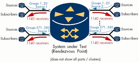
As in the tests before, the CRS-1 did not lose any packets – whether unicast or multicast. It controlled the 58 PIM links, built the distribution trees for 580 multicast groups with two sources and 57 subscribers each, and sent 330 million multicast pps downstream. Another 192 million unicast packets were exchanged in parallel.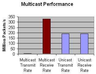
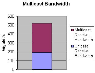
In the second part of the test, the CRS-1 worked as the RP, in addition to the tasks it had to do before. The results were identical to those of part A.
To summarize, we were unable to overload the router with multicast traffic or multicast routing. The test showed that the CRS-1’s multicast performance complements its unicast forwarding speed, easily reaching more than 300 million pps per chassis.
Next Page: Class of Service
Test Objectives
Verify correct implementation of IPv4 Differentiated Services (DiffServ).
Test Setup
For detailed information on the test setup, please see the complete Methodology, page 30.
The test was divided into two parts:
The links were oversubscribed using constant data-rate traffic flows. The queue management of the CRS-1 had to handle the resulting congestion, prioritizing streams accordingly.
Queue management was evaluated under burst conditions. We determined whether bursty traffic has an influence on EF-class traffic.
The test used five traffic classes, each with different packet sizes:
Table 4: Packet size definitions for DiffServ classes
DiffServ-Class | DiffServ-Name | Class Name | Packet Size |
EF | Expedited Forwarding | Premium | 60 Byte |
AF11 | Assured Forwarding Class 1 | Gold | 40 Byte |
AF21 | Assured Forwarding Class 2 | Silver | 552 Byte |
AF31 | Assured Forwarding Class 3 | Bronze | 576 Byte |
BE | Best-Effort | Best-Effort | 1500 Byte |
Six of the 58 ports were not configured to receive data this time; they were used as transmit-only ports sending data to all the others, resulting in over-subscription. Under congestion, the router should drop only low-priority frames.
IPv6 does not use DiffServ in the same way, so this test dealt with IPv4 only.
Table 5: Traffic load definitions for linear DiffServ streams
Class Name | Bandwidth Limitation on Router | Bandwidth Transmitted From Traffic Generator (for OC-192) Step A | Bandwidth Transmitted From Traffic Generator (for OC-192) Step B |
Premium | 0.5 Gbit/s | 0.5 Gbit/s | 0.5 Gbit/s |
Gold | 35% of line speed without EF | 3 Gbit/s | 3 Gbit/s |
Silver | 25% of line speed without EF | 2 Gbit/s | 2 Gbit/s |
Bronze | 25% of line speed without EF | 2 Gbit/s | 3 Gbit/s |
Best-Effort | (rest = 15%) | 3.5 Gbit/s (1 Gbit/s coming from the extra ports) | 2.5 Gbit/s (1 Gbit/s coming from the extra ports) |
If traffic in one DiffServ class exceeds the limit, it should not be remarked by the router (this is typically an edge router function) but will be forwarded according to queue configuration. The purpose of this test was to verify congestion handling and queuing, not remarking.
First test run:
All classes except Best Effort were transmitting within their configured limits.
Packet loss was expected only for the Best Effort class.
The router did not lose any packets in the EF and AF1, AF2, AF3 classes.
There were also no sequence errors in the EF and AF classes.
The maximum latency in any of the guaranteed classes was 0.23 milliseconds.
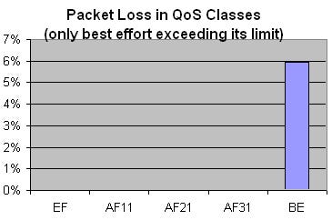
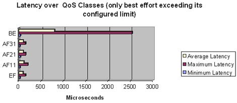
In a second step, we increased the AF31 stream bandwidth by 1 Gbit/s – exceeding the configured limit for this class. At the same time, we reduced the Best Effort stream bandwidth by 1 Gbit/s. The total over-subscription rate remained unchanged. We expected that the switch should keep track of configured percentages, dropping more packets in the AF31 class violating its limit, than in the Best Effort class.

Part B: Bursty Traffic
In this part, we observed packet loss and latency of premium (EF) traffic while sending bursts of traffic on the other traffic classes.
Table 6: Traffic load definitions for Diffserv traffic bursts
DiffServ Class | Average Bandwidth | Burst Load | Burst Length (consecutive packets) |
EF | 0.5 Gbit/s | - | - |
AF11 | 1 Gbit/s | 1.5 Gbit/s | 5 |
AF21 | 1.5 Gbit/s | 2.0 Gbit/s | 10 |
AF31 | 2 Gbit/s | 4 Gbit/s | 25 |
BE | 3 Gbit/s | 6 Gbit/s | 50 |
The router should prioritize EF traffic in all conditions. No packet should be lost in the EF traffic class, and latency should not be increased even when the link is oversubscribed. Traffic in all other classes should be forwarded as defined, dropped if necessary.
The router behaved as expected. No packet loss was observed in the Premium, AF11, and AF21 traffic classes. Latency for the prioritized classes was unaffected when the links were oversubscribed. In all test runs, traffic in the Best Effort and AF31 classes was dropped only if necessary.
In the second step (static linear flows with AF31 over-subscription), the AF31 streams lost much more traffic than the Best Effort streams because the router was configured for “bandwidth percentages.” The AF31 stream greatly exceeded its percentage, but the Best Effort stream exceeded it by only a very small amount.
The system mastered the traffic burst profile, too. The maximum latency for the EF and AF classes was increased by 10 percent as compared to the static traffic profile.
In all test runs, the AF11 class showed a slightly higher maximum latency (+ 20 µs) compared to the other AF classes. Cisco commented that this happens because the AF11 class has smaller packets at a higher rate than do the other AF classes. After the packets are de-queued from their respective queues they go into a FIFO towards the line interface module (PLIM). If it happens that the other two AF classes both put packets into the FIFO while AF11 just has exceeded its quantum, the next AF11 packets see little higher latency, which is reflected in the higher maximum latency.
Next Page: Software Maintenance
Test Objectives
Assess the service interruptions caused by software upgrades and hardware module exchanges.
Test Setup
For detailed information on the test setup, please see the complete Methodology, page 34.
Carriers expect that a huge core router like the CRS-1 basically never needs to be taken out of service voluntarily for any maintenance activity. Also, no single failing component should cause any outages. We verified whether the router confirms both expectations:
We upgraded and downgraded an important software package;
We removed and reinserted a primary route processor;
We removed and reinserted a secondary route processor;
We removed and reinserted a fabric card without previous software shutdown;
We exchanged a fabric card with software shutdown;
We removed and reinserted a linecard.
In all of these steps, we loaded the system with a lot of BGP routing and IPv4/IPv6 forwarding activity – we reran the eBGP peering test, forwarding traffic at line speed over 1.5 million routes. This way we were able to verify the real service impact of any service activities on the routing and forwarding performance of the CRS-1.
Software Upgrade
Cisco’s IOS-XR software is highly modular. For the upgrade and downgrade test, we chose the routing (BGP, OSPF, etc.) software package because it is a module typically modified with changing IETF guidelines and requirements, and because its non-availability would be fatal to the system. We did not test an upgrade/downgrade of the base software (the underlying operating system infrastructure software).
We upgraded the software package from version 2.0.0 to 2.0.2. Afterwards, we downgraded back to 2.0.0. This test was pretty aggressive, because the system had to exchange the BGP code on the primary route processor and restart all the BGP sessions while continuing to forward packet streams and keeping BGP neighborships.
The result was quite amazing: During the upgrade, the router lost just 24 IP packets on all interfaces, forwarding at a rate of 560 million pps – equivalent to 120 nanoseconds, or 0.00000012 seconds of service interrupt. In the downgrade test, the system lost only 9 packets equivalent to 45 ns. These lost packets were kind of odd, as we only saw them on one of the Agilent stacks (the one with 18 interfaces) and in one of the test runs: When we repeated the procedure a second time, there was no packet loss at all.
Out-of-sequence packets were not seen in any of the test runs, and the forwarding latency did not increase. The whole software upgrade or software downgrade process for both primary and secondary route processor took around 90 seconds to complete.
Hardware Module Exchange Procedure
In the same test configuration as before, we removed and reinserted critical and redundant hardware components.
Results are as follows:
Table 7: Service interruption caused by hardware exchanges
Test | Packet Loss Equivalent (time) | Maximum Latency (�s) | Out of sequence packets |
Secondary Route Processor removed/reinserted | 0 | 104 | 0 |
Fabric card removed/reinserted without previous software shutdown | 190 ms | 112.1 | 0 |
Fabric card removed/reinserted with software shutdown | 0 | 110.2 | 0 |
Line card removal/reinsertion without traffic | 0 | 109.9 | 0 |
Primary route processor removal/reinsertion | 0 | 114.4 | 0 |
Summarizing these results, route processors and fabric cards can be exchanged live without any impact on routing and forwarding. Naturally, the system needed a short time (190 ms) to recover when we removed a fabric card without previous software shutdown.
Next Page: MPLS Scaleability
Test Objectives
Verify the functionality and scaleability of the router under test as an MPLS label switch router (LSR) using RSVP-TE.
Test Setup
For detailed information on the test setup, please see the complete Methodology, page 35.
The system under test is used in the core backbone, not at the edge. Regarding MPLS, it works as an LSR (Label Switch Router) and is not involved in VPN services, at least in its current hardware and software configuration. The CSR’s main function is to negotiate transport MPLS labels, and to maintain traffic-engineering tunnels – so that’s what we tested:
The test stressed the control plane by establishing a total of 57,000 RSVP-TE tunnels.
We checked the forwarding performance over MPLS by sending wire-speed traffic through all the tunnels.
Furthermore, we verified the traffic prioritization and queuing performance by sending premium and best-effort traffic through the tunnels (using the EXP bits in the MPLS label header), over-subscribing the destination ports.
This test case was carried out with a different Agilent N2X software release on one of the clusters, the 6.4 beta release, because it offered new MPLS enhancements that made it easier to create RSVP-TE traffic meshes. The other cluster ran standard software 5.1.1. Creation of the RSVP-TE LSPs nevertheless took a large amount of time (hours) using the 5.1.1 software, while the 6.4 beta release took minutes to create 1,500 LSPs per port.
Results
{Table 8}
All LSPs were established successfully. Some of them were dropped 30 seconds after starting the test; this was attributed to instability in the Agilent N2X RSVP-TE implementation.
The router under test established all RSVP-TE tunnels. Throughput reached wire-speed for all RSVP-TE tunnels. The prioritized (Traffic Engineering) tunnels forwarded all packets without loss and showed minimum latency. Packet loss during an over-subscription test was observed only in the best-effort streams, as expected.
Next Page: Service Provider Feedback
After the initial test methodology had been developed by EANTC in September 2004, Light Reading invited a panel of leading service provider experts to comment on the test plan. It was extremely important to make sure that all test cases reflect current carrier test practices and are scaled to meet future service provider core backbone requirements. We wanted to make sure that each single test case is realistic and valid.
Representatives of five large carriers – including Ernest Hoffmann, VP of Engineering at FiberNet Telecom Group Inc. (Nasdaq: FTGX); and Jack Wimmer, VP of Network Architecture and Advanced Technology, and Glenn Wellbrock, Director of Network Technology Development, at MCI Inc. (Nasdaq: MCIP) – replied with very detailed comments. Also responding was SBC Communications Inc. (NYSE: SBC). With some of the contacts, there were lively discussions going on over two weeks via email and conference calls. This way we were able to strengthen the test plan, making it representative for a multitude of service provider environments.

Forwarding Scaleability
Our panelist service providers suggested:
“We consider 15 million flows to be a good number, exceeding today’s requirements.”
“60 seconds worth of testing is not adequate. Test runs should be orders of magnitude longer to determine if extended use can lead to software errors such as memory leaks.”
“15 million flows don't seem like enough to test a 40-Gig router.”
“Will a distinction be made between the latency of the 1st packet per flow vs. 2nd+ packet of a flow? (To see the route-lookup cost.)”
“Definition of wire speed on a POS link: What is the value of ‘wire-speed’ for OC-192 and OC-768?”
“POS byte stuffing: This will be extremely difficult to achieve given that there are 22k IP addresses per port and you need to ensure that no byte stuffing occurs in packets, header, or checksum. Do you have a process to automate this?”
“56 OC-192s and 2 OC-768s: We recommend that the interfaces corresponding to each test cluster are interleaved to distribute the load across the switch fabric.”
We took the following actions:
15 million flows is equivalent to 5 Kilobytes per user per second in a fully loaded system, which seems to be appropriate, so we decided to leave the test plan unmodified.
We increased the test run time to 300 seconds.
We measured the maximum latency of each flow, making sure that no single packet took an excessive time.
The definition of wire-speed rates in packet-over-Sonet is a real threat because of the HDLC line encoding. Unpredictable byte stuffing can occur in the system under test because the router modifies each IP packet (decreases time to live field, updates checksums), and HDLC-relevant bit patterns can appear in addition, so the bit rate may actually increase while packets travel through the router, leading a bit stream exceeding egress line bit-rate. We did not find a way to calculate and predict the HDLC byte stuffing effects, so we had to run latency tests at a reduced rate of 98 percent throughput.
We interleaved port-to-analyzer links to make sure that the flows were distributed across the chassis of the system under test.
Routing Scaleability
Service providers suggested:
“Can we use more than one source IP address per route in order to simulate the real-world better? Perhaps use the same methodology (flows, packet size variation) as in the first test?”
“It will be very interesting to see if this next generation of router can do more than 1 million BGP routes and route traffic to all of them!”
“Routing re-convergence tests are very important.”
“Even if there is only one physical router available for the test, can you verify re-convergence with a logically split router configuration?”
We responded as follows:
We modified the BGP test to use the same Internet mix packet streams as in the other test cases.
The one-to-one IP address/route relationship was not changed, because it would have been too difficult to keep track of the statistics.
We increased the number of unique routes to 1.7 million in total (23,000 IPv4 and 7,000 IPv6 per port) and sent traffic over each of the routes.
Unfortunately, there was only one system available for the test. In the current software release, virtual routers are not yet supported. So we could not test routing re-convergence with two real systems. But we extended the test plan to cover BGP convergence using the Agilent emulator.
Availability
Naturally, the carriers showed special interest in the high-availability test:
“Redundant and active control modules should be pulled as well, not just interface modules.”
“In the hardware module exchange procedure, if the device has both removable linecards and modules within the linecards, I've found it interesting to test removal of both.“
“Software maintenance testing: We recommend the following amendment to the Expected Results section – ‘We expect that a software upgrade/downgrade influences forwarding and routing only to the extent claimed by the vendor, prior to testing.’ "
“Should go without saying, but really clarify what the vendor says will happen. Hitless should mean hitless.”
We took the following actions:
The hardware redundancy tests were extended to all removable redundant units.
For all software upgrades and hardware exchanges claimed to be hitless, we made sure to measure the exact results, and asked the vendor about his claims before the test case started.
IPv6
There were no specific remarks to the IPv6 tests. However, when directly asked, the service providers agreed that IPv6 is a “very important” implementation feature for a core router designed to last for the coming years.
Multicast
Suggestions included here:
“I wish some more test cases could be added to provide more insight on the multicast forwarding capacity/performance limits, for example, more multicast groups, different multicast traffic loads.”
“I don't really have a good estimate on the multicast group number. I wonder how you found 580 is the max scale here. I'm thinking the number could be higher if multicast is to be supported for RFC2547 (BGP/MPLS VPNs).”
We didn’t extend the multicast test because of lack of test time. We agreed that the number of multicast groups should be higher if customer-specific multicast is transported through MPLS VPNs. This test case related to native IP, however, so we left the number of groups unchanged.
MPLS
Responses included:
“MPLS scaleability test: We would suggest adding a churn test to assess teardown and re-establishment.”
“No tests of MPLS fast reroute?”
“No test to see LSP re-convergence while a cable or module gets pulled?”
“Is it possible to test provider edge (PE) VPN functionality?”
We reacted to these very valid requests:
Unfortunately, the test equipment was the limiting factor on the tunnel teardown and re-establishment times. We had to drop the test because invalid results were found during pre-staging.
We would have loved to test MPLS re-convergence – for LSP convergence we would have required at least two routers, for fast reroute even three routers. So we had to decide not to add the test.
Security and QOS
Their questions:
“How far into the packet does this Access Control List (ACL) look? Does it check just source and destination addresses, or does it go into the protocol type and/or port information?”
What does a typical ACL entry look like? Does it include protocol and port? I believe a mix of src/dst IP address and protocol/port ACLs would make the test case more realistic.”
Our answer:
Two contributors had exactly the same request. We included TCP and UDP ports in the ACL test.
You May Also Like


